EXPLORE THE POSSIBILITIES
Our Virtual Home Experience is an interactive tour demonstrating how each of Steffes's ETS product offerings increase your comfort and your home's efficiency.


On this page:
Steffes’s Comfort Plus and Serenity furnaces combine forced air heating with our Electric Thermal Storage (ETS) technology to heat your home. Unlike traditional forced air furnaces, Steffes furnaces pull electricity from the grid to heat ceramic bricks within their cores. That heat is circulated throughout your space exactly when it needs it, ensuring comfort all day, every day.

![]()
Steffes’s Serenity forced air furnace (4200 series) is the smallest unit in its product family, featuring 72 ceramic bricks and eight heating elements. Its modest footprint makes it the perfect heating solution for small homes.

![]()

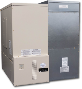
Steffes’s line of Comfort Plus forced air furnaces (4100 series) holds between 108 and 204 ceramic bricks and utilizes between 8 and 16 heating elements. These furnaces are ideal for heating large homes.
A dealer near you will recommend a Steffes furnace that fits your home’s heating needs, taking into account factors such as square footage, insulation value, and more!
Our Virtual Home Experience is an interactive tour demonstrating how each of Steffes's ETS product offerings increase your comfort and your home's efficiency.
 BENEFIT FROM A LOWER HEATING BILL.
Your Comfort Plus or Serenity furnace can be set to pull electricity from the grid when the demand is low. That could be midday, when most are away at work or school, or midnight, when most are sound asleep. If your utility company offers a special rate for electricity used during this time, you could save money on your heating bill!
STEFFES FURNACE + HEAT PUMP = CONSISTENT COMFORT
Heat pumps provide efficient, low-cost heating and cooling, but many struggle to provide adequate comfort in cold climates.
What happens when you add a Steffes forced air furnace to the mix? Magic!
Together, a Steffes furnace and a heat pump will meet your family's heating needs, while remaining efficient and inexpensive, no matter the outdoor temperature.

All Steffes ETS products undergo rigorous safety testing by UL Solutions.
The Comfort Plus and Serenity forced air furnaces are equipped with internal safety devices to protect from overheating, and we ultra-insulate the brick cores to minimize the furnaces’ surface temperatures.
Steffes’s optional accessories afford you more flexibility in how you use your Serenity or Comfort Plus forced air furnace. The Transceiver allows you to adjust a number of settings while you’re away from home, and the elevation stand protects your Comfort Plus from water damage.
This accessory connects your Serenity or Comfort Plus to a mobile device, allowing you to adjust a number of settings remotely using the Steffes Connect app. It comes in different sizes and can be mounted at different locations inside or outside your home; a professional will recommend the right size and location for your situation.

Connect with member services at your local power company.
They may offer special rates, rebates, or incentives for using Steffes ETS products in your home or business.

Questions? Contact us!


