100 percent efficient
Clean, Safe, Reliable
Easy to operate
Minimal maintenance required
Built-in circuit breakers eliminate need for a service disconnect
Optional air handler and static heat recovery unit available
Auxiliary load control capabilities
Five-year limited parts warranty
Full list 5100 Series Comfort Plus Hydronic Furnaces features
Comfort Plus Hydronic Furnaces Specifications Chart (5100 Series)
| MODEL |
5120 |
5130 |
5140 |
| Charging Input (See Note 1) |
14.0 kW |
19.2 kW |
24.8 kW |
28.8 kW |
37.2 kW |
38.4 kW |
45.6 kW |
| Single Feed: Minimum Circuit Ampacity 240 V (Includes 25% Derate for Continuous Load) |
84 amps |
110 amps |
140 amps |
160 amps |
204 amps |
210 amps |
248 amps |
| Element Current Draw |
59 amps |
80 amps |
104 amps |
120 amps |
155 amps |
160 amps |
190 amps |
| Element Circuits Required (See Note 2) |
1-20 amp
2-30 amp |
1-30 amp
2-40 amp |
1-40 amp
2-50 amp |
4-40 amp |
4-50 amp |
4-50 amp |
4-60 amp |
| Pump and Blowers/Controls Circuit Required |
1-15 amp (10 amps maximum load)
|
| Pump Voltage |
120V (neutral conductor required) |
| Blower/Controls Voltage |
240V or 208V |
| System Dimensions (W x D x H in inches) |
29 x 46.5 x 46 |
29 x 46.5 x 57 |
29 x 46.5 x 68 |
Storage Capacity (See Note 3)
|
120 kWh (409,440 BTU) |
180 kWh (614,160 BTU) |
240 kWh (818,880 BTU) |
Approximate Installed Weight (See Note 4)
|
2,218 lbs |
3,046 lbs |
3,894 lbs |
Number of Brick
Whole Brick
Half Brick |
105
6
|
150
12
|
198
12
|
| Pipe Size – Water Inlet/Water Outlet |
1” |
| Output Water Temperature Selection Range |
50°F/10°F to 185°F/85°C |
| Maximum Working Pressure |
20 PSIG requires 30 PSI Pressure Relief Valve (Standard)
Optional: 60 PSIG req. 75 PSI Pressure Relief Valve; 125 PSIG req. 150 PI Pressure Relief Valve |
| Minimum Flow Rate (primary loop) |
1 GPM per 10,000 BTU of required output at 20°F temperature rise (10 GPM maximum) |
|
Maximum Maintainable Heat Loss (See Note 3)
8 Consecutive Charge Hours (BTU/Hr)
12 Consecutive Charge Hours (BTU/Hr)
6/4/6/8 Charge Strategy (BTU/Hr)
|
20,414
30,621
30,621
|
27,996
41,994
41,994 |
34,175
45,566
54,242 |
41,994
62,991
92,991 |
49,212
65,615
81,363
|
55,992
83,988
93,988 |
65,615
87,487
99,738 |
| Internal Pressure Drop (assuming 50% glycol mix) |
.1 ft @ 2 GPM
.2 ft @ 4 GPM |
.4 ft @ 6 GPM
.7 ft @ 8 GPM |
1.1 ft @ 10 GPM
|
Note 1: Standard configuration (240V) systems can be connected to 208V; however, the charging input of the system will derate by 25%. If 208V specific charging voltage is required, it is available as a special factory order. For 277V systems, refer to the 7100 series.
Note 2: Unit is factory configured with multiple line voltage, single phase circuit connections. If single feed to the element and blowers controls circuits is desired, an optional single feed kit is available. Phase balancing is recommended when making connections in 3-phase applications.
Note 3: The size and heating ability of the system required for an installation is dependent on the heat loss of the area and the power company’s off-peak hours. In addition, if the unit is not installed within the heated area, heat lost statically must be taken into account when sizing a system. Contact Steffes for assistance in selecting an appropriately sized system.
Note 4: Contact a building contractor or architect if you have structural weight concerns of the installation surface selected. Adhere to all national and local electrical and building code placement requirements for electrical heating appliances.
Comfort Plus Hydronic System Installed with a Heat Pump
 Heat pump systems are known as one of the most efficient methods of heating and cooling. Utilizing a Comfort Plus Hydronic unit with a heat pump allows the heat pump’s high efficiency to be combined with off-peak electric rates making this heating and cooling system the lowest operation cost option. In addition, the Comfort Plus Hydronic unit ensures comfort regardless of outdoor temperature.
In heat pump applications, the Comfort Plus Hydronic unit replaces the resistance strip heat or secondary heat, which is typically required as a supplement or backup to heat pump systems, with low cost, off-peak stored heat. As outside temperatures decline the stored heat in the Comfort Plus Hydronic unit is used in conjunction with the heat pump’s heating capacity to satisfy comfort requirements. During on-peak hours or when the demand for heat is at the point where the heat pump alone cannot satisfy the heating requirements, the stored heat is used to supplement the heat pump. The Comfort Plus Hydronic unit allows the heat pumps efficiency to be utilized even during cooler outdoor temperatures.
To interface the Comfort Plus Hydronic unit to a heat pump, the Steffes Air Handler is required. The Steffes Air Handler not only allows the Steffes Comfort Plus Hydronic furnace to supplement the heat pump and provide comfort modulation when needed; but, it also will direct the heat lost statically through the furnace’s outer panels into the ductwork for delivery to the living space (automatic static heat recovery).
The Comfort Plus/Heat Pump system offers significant benefits:
- Provides great comfort 24 hours a day
- Provides for a high efficiency, low cost heating and cooling system all in one
- Optimizes system performance by allowing the heat pump’s efficiency to be fully utilized
- Eliminates the cool discharge air temperatures associated with heat pump systems during low outdoor temperatures
- The Comfort Plus/Heat Pump combination, when used with off-peak electric rates, is the most economical heating and cooling system available.
How the System Works
- The room thermostat in the home is set to desired comfort level. If room temperature decreases below the room thermostat set point, the system is energized to deliver heat.
- Upon a heat call from the room thermostat, the heat pump’s outdoor compressor unit is energized and warms the A-coil in the return air duct of the Comfort Plus unit. At the same time, the Comfort Plus unit’s supply air blower is energized.
- The supply air blower draws air from the home across the air filter and the heat pumps A-coil extracting heat from the coil.
- A sensor monitors air temperature after the A-coil. If the air temperature is warm enough to provide comfort to the homeowner (generally 90° F or higher), the supply air blower simply delivers the warm heat into the home through the supply air duct.
- If air temperature after the heat pump coil is below a comfortable level (generally less than 90° F), the Comfort Plus unit’s core blower will modulate low cost, “Off-Peak” stored heat into the duct stream so comfortable heat (generally 90° F or higher) can be delivered into the home.
- Since heat pumps generally have an operating efficiency of 150%-300% or greater (depending on outdoor temperature), the Comfort Plus system allows the heat pump to satisfy as much of the heating requirement it can on its own. If the heat pump doesn’t have the ability to satisfy comfort and space heating requirements, the Comfort Plus system modulates into the duct the precise amount of its stored, low cost, off-peak heat to ensure comfort for the user at all times. Combining the heat pump’s efficiency with the off-peak Comfort Plus system yields very low operating costs for the end user along with great comfort.
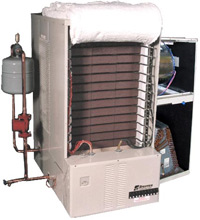
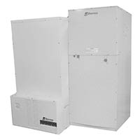
Hydronic Furnace Air Handler
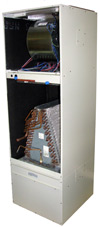 The Steffes Air Handler is an optional device designed to interface to the Comfort Plus Hydronic heating system to allow it to provide forced air heating in addition to radiant heating.
With an air handler, the furnace can provide forced air heating as either a stand-alone system or a supplement to other ducted heating systems such as a heat pump.
When used with a heat pump, the Comfort Plus Hydronic furnace can be used as the back-up heat source and to provide comfort modulation. Heat pumps can be operated to much lower temperature allowing for full utilization of its efficiency and optimizing system performance.
A duct sensor constantly monitors outlet air temperature and modulates the precise amount of stored off-peak heat needed into the duct to eliminate cool and uncomfortable discharge air temperatures. The air handler will also direct the heat lost statically through the furnace’s outer panels into the ductwork for delivery into the living space (automatic static heat recovery).
The internal controls of the Comfort Plus Hydronic furnace automatically regulates the operation of the air handler. The Steffes Air Handler includes a return plenum supply air blower and plenum, water coil and air filter. It is painted and fully insulated.
Steffes Air Handler Features:
- Connects directly to the Comfort Plus Hydronic Unit (right side)
- Provides option for ducted heating and cooling with Comfort Plus Hydronic Furnace.
- Accepts most any coil
- Provides automatic static heat recovery of heat coming off Comfort Plus Hydronic Furnace outer panels
- Factory pre-wired to interface with Comfort Plus Hydronic control logic and output temperature sensing (no additional electrical components required)
- Variable speed supply blower to ensure comfort, optimum performance and operational cost savings
Variable Speed (ECM) Blower:
The optional Steffes Air Handler is configured with a variable speed (ECM) blower to provide extra comfort as well as added cost savings. The variable speed blower delivers a more consistent, even temperature throughout the house to provide a more comfortable environment. because it is more efficient to operate than a typical standard blower system, it consumes less energy to reduce the overall operational cost. Other exceptional benefits include:
- Quiet operation with automatic ramp up and down speed control
- In “Fan Only” mode, the blower operates in low speed providing uniform air circulation and constant air filtration
- Improved humidity control
Steffes Air Handler Specifications:
| |
1/2 HP, 60 HZ Variable Speed (ECM) Air Handler |
1 HP, 60 HZ Variable Speed (ECM) Air Handler |
| Order Item Number |
1302132 |
1302134 |
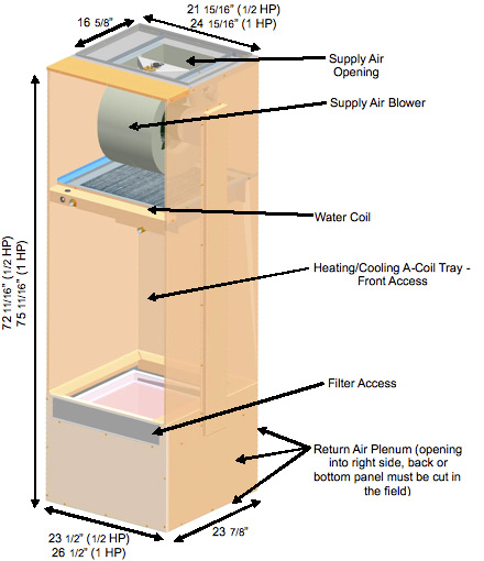
| Dimensions (H x L x D) |
72 11/16″ x 23 1/2″
x 23 7/8″ |
75 11/16″ x 26 1/2″
x 23 7/8″ |
| Approximate Weight |
200 lbs |
225 lbs |
| Maximum Static Pressure (inches water column) |
.75 inches H2O |
.75 inches H2O |
| Maximum Water Coil Output |
60,000 BTU/hr |
90,000 BTU/hr |
| Maximum Outlet Temperature |
120º F |
120º F |
| A-Coil Tray – Front Access (H x L x D) |
30″ x 22 5/16″ x 22 3/4″ |
33″ x 25 5/16″ x 22 3/4″ |
| Filter Dimensions |
20″ x 20″ x 2″ |
25″ x 20″ x 2″ |
| Voltage |
240/208 VAC |
240/208 VAC |
| Wattage |
560W |
1,050W |
| CFM Ratings |
1000, 1200, 1400, 1600 |
1200, 1400, 1600, 2000 |
Steffes Air Handler Dimensions
Residential Hydronic Furnace Static Heat
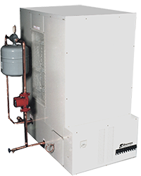
During operation of the Comfort Plus Hydronic unit, there will be some heat which passes from the core and radiates through the outer surfaces of the Comfort Plus Hydronic unit. If the Comfort Plus Hydronic unit is located in an area where this amount of radiant heat is excessive or not desired (such as a small room or an unheated basement), the Static Heat Recovery Unit can be used to move the majority of this heat to a more desirable location. Utilizing this option can maximize efficiency when the system is installed in an area with minimal heating requirements such as a utility room or garage. In applications using the Steffes Air Handler, the Static Heat Recovery Unit would not be needed as the Steffes Air Handler will provide for automatic heat recovery as well.
- Connects directly to a Comfort Plus Hydronic Unit (left side)
- Hardware and wiring is included for easy installation
- Comfort Plus on-board controls automatically regulate operation
Static Heat Recovery Unit Specifications:
| Maximum Outlet Temperature |
190º Fahrenheit |
| Maximum Static Pressure |
.15 inches H20 |
| CFM @ .15 SP |
130 |
| Voltage |
240/208 VAC 60 HZ |
| Wattage |
130 |
| HP |
.1 |
Static Heat Recovery Unit Dimensions


 The Steffes Air Handler is an optional device designed to interface with the Comfort Plus Hydronic (5100 Series) Furnace to provide forced air heating as a standalone furnace or as a supplement to other ducted heating systems.
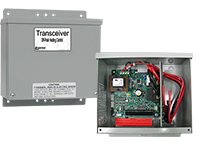 Steffes Transceivers regulate operation of Steffes heating systems and other electric loads to take advantage of off-peak electricity. When the transceiver receives a signal, its internal relays will activate to regulate operation of directly connected loads. At the same time, it will transmit a wireless PLC signal to any device having a corresponding Steffes receiver. This transceiver can also transmit outdoor temperature information to Steffes heating systems for automatic regulation of heat storage in the bricks.
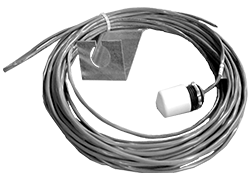 This accessory provides outdoor temperature information for automatically regulating brick core temperature.